

|
|
|
|
Most of this information is taken from the Toyota engine repair manual for the 4A-GE engine fitted to normally aspirated Mk1 MR2s.
The ECU (Electronic Control Unit) contains a self-diagnosis system which detects malfunctions and abnormalities with the engine electrical systems. These could be present in the wiring, the sender unit (e.g. throttle position sender or distributor), in the ECU itself, or any combination of those three things. Therefore it can be quite a complex process to identify and rectify the fault. Don't let that put you off checking these things for yourself though - you may be able to find the fault and fix it easily. Even if not, you'll have a better idea of what is wrong which may help if you then take the car to a garage for repair.
If the ECU detects a problem it indicates this by keeping the check engine warning light illuminated when the engine is running. See my page on instrument panel warning lights to identify the check engine warning light. It may be the case that the engine stops and will not restart if you have one of these problems, which means you won't be able to check if the check engine warning light illuminates when the engine is running! If this is the case you may wish to follow the steps below anyway to see if you have any electrical system problems.
The ECU can flash the check engine electrical system warning light a certain number of times for each error it has stored. To make the ECU do so you need to short two terminals in the diagnostics terminal. The latter is easily accessible at the rear of the engine bay, and it can be seen in the photos on my JR air filter installation page. The warning light will flash the number of times equal to the error code with a 2.5 second pause between each error code and a 4.5 second pause before starting the sequence again. For example, if you have error conditions 3 and 5 you would see the following on the check engine warning light when you short the two diagnostic connector terminals:
3 flashes - 2.5 second pause - 5 flashes - 4.5 second pause - 3 flashes - 2.5 second pause - 5 flashes - 4.5 second pause...
If you have just error code 6 then you will see:
6 flashes - 4.5 second pause - 6 flashes - 4.5 second pause...
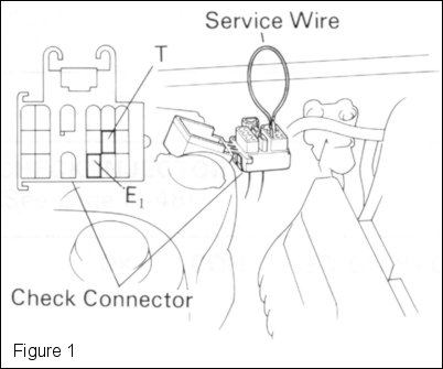 The full procedure for obtain the error codes is as follows:
The check engine electrical system warning light will now flash the error code(s) it has stored in the manner descibed above.
The following table lists details of the diagnostic codes.
| Code | System | Diagnosis | Trouble Area |
|---|---|---|---|
| 1 | Normal | There are no problems. | None. |
| 2 | Pressure sensor signal | Open or short circuit in pressure sensor. |
|
| 3 | Ignition signal. | No signal from ignitor four times in succession. |
|
| 4 | Water thermo sensor signal | Open or short circuit in coolant temperature sensor signal. |
|
| 5 | There is no code 5 (shades of the Monty Python "Bruces" sketch). | ||
| 6 | RPM signal. | No Ne, G signal (engine revolution sensor) signal to ECU within several seconds after engine is cranked. No Ne, G signal (engine revolution sensor) signal to ECU within several seconds after engine reaches 1,000rpm. |
|
| 7 | Throttle position sensor signal. | Open or short circuit in throttle position sensor signal circuit. |
|
| 8 | Intake air thermo sensor signal | Open or short circuit in intake air temperature sensor signal. |
|
| 9 | Vehicle speed sensor signal | Speed sensor indicates 0 km/h for several seconds when engine rpm is above 2,300 or 2,800 and manifold pressure is higher than specified. |
|
| 10 | Starter signal. | No STA signal to ECU when engine is running over 800rpm. |
|
| 11 | Switch signal. | Air conditioning switch on or IDL points in the throttle position sensor off. Not registered in memory. |
|
After repair of the troubled area, the diagnostic code(s) retained in memory by the ECU can be cleared by disconnecting the battery or removing the 7.5A AM2 fuse in the main fusebox near the battery for 10 seconds or more (depending on ambient temperature), with the ignition switch OFF. Removing the fuse is preferable as it is easier and will not reset the clock, alarm etc.
If the codes are not cleared, then they will appear with any new code(s) if a malfunction occurs in the future. Obviously this is not desirable because the new fault(s) cannot then be identified easily.
After clearing the code(s), the vehicle can be road tested and then the diagnostic system checked to make sure the system now reports code 1 (normal).